Click here to get the description of the new Munic Box 3
Click here to get an overview of the standard available fields
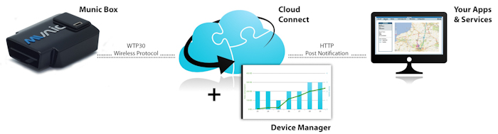
Munic.Box is connected to your car and monitors in real time a large numbers of parameters such as position, acceleration ...
Munic.Box monitor extensively the states of the vehicle and the event of driving, each data is stored in fields.
Below are defined the different type of data
Journey data
Munic.Box integrates the notion of Journey, several parameters are then accumulated and recorded at the end and the start of a trip.
GPS
Using the internal GPS, the OBD dongle offers multiple location based services such as the acquisition of speed, heading, mileage.
Driver behaviour data
Thanks to its in-built accelerometer, the device helps you understand how your vehicles are driven. By detecting brutal acceleration, deceleration and cornering the device can send you precise data on your driver’s style.
Engine & car diagnostic data
Munic.Box also includes a ready-to-use OBD protocol stack. It gives you access to all standard car diagnostic information such as engine RPM, speed, mileage, fuel consumption, Vehicle Identification Number (VIN), and more...
No specific OBD knowledge is required!
Fields contain the following property:
name - Name of the fieldfield - Integer - ID of the fieldfield_type - Type of the field. unknown | boolean | integer | decimal | string | base64 size- Maximum size of the field in bytesack - Does this field need to be acknowledged? If left blank (null), no ack is required, if 0 an ack is sent at once, if a positive integer, the ack is sent within the time specified (in seconds).Below is an example of Field:
{
  "field": 8,
  "name": "GPS_SPEED",
  "size": 3,
  "ack": 1,
  "description": "Stores the last valid speed of the GPS in 1/1000th knots.",
}
The possibility for the user to create its own fields is restricted, please ask our support for more details.
Munic.Box monitors the movement and the RPM of the vehicle and then detects if the engine is running or not. Please note that this simulation of ignition is not valid for hybrid and non OBD compliant vehicles.
| Conditions | Ignition State |
|---|---|
| Ignition OFF and Movement and RPM detected | OFF -> ON |
| Ignition ON and No Movement and no RPM detected after timeout | ON -> OFF |
Using the built-in accelerometer, the OBD-II dongle is able to detect every movement of the vehicle. The movement state is activated, when movement is detected during more than 1 minute (to prevent glitches due to unrelated vibrations).
The definition of journey is based on the ignition (engine running or not) detection. A journey starts when ignition switches from OFF to ON, a journey ends when ignition switches from ON to OFF.
| Ignition state | Journey State |
|---|---|
| Ignition OFF -> ON | Journey starts : 0 -> 1 |
| Ignition ON -> OFF | Journey ends : 1 -> 0 |
With MorpheusSDK, more specific journey definition can be developed.
In combination with the beginning and the journey' end, Munic.Box is also monitoring the movement of the unit (if the accelerometer detects a movement or a non movement for more than 2 minutes), thus enabling the detection
| Journey State | Movement State | Results |
|---|---|---|
| Journey ON | Vehicle not moving after timeOut | Vehicle is Idling |
| Journey OFF | Vehicle moving | Vehicle is Towed |
The different vehicle states are described in one field, MDI_VEHICLE_STATE, described below:
| Field Name | Format | Description | Size |
|---|---|---|---|
| MDI_VEHICLE_STATE | string | ‘previous state :current state’ (0:journey on, 1:journey off, 2:idling, 3:tow away) | 3 |
Several data are accumulated based on the beginning/end of a journey. Here are a list:
| Field Name | Format | Description | Size |
|---|---|---|---|
| MDI_JOURNEY_STATE | int | Returns 1 a journey is started and 0 if not | 4 |
| MDI_JOURNEY_TIME | second | Returns the latest journey time | 4 |
| MDI_IDLE_JOURNEY | second | Returns the total time spent in idling (no movement) during the latest journey | 4 |
| MDI_DRIVING_JOURNEY | second | Returns the total time spent driving during the latest journey | 4 |
| MDI_ODO_JOURNEY | km | Gives the total distance driven during the latest journey | 4 |
| MDI_OVERSPEED_COUNTER | int | Gives the number of overspeed during the latest journey | 4 |
| MDI_MAX_SPEED_JOURNEY | milliknots | Returns the highest speed reached during the latest journey | 4 |
Based on the built in 40 channels GPS receiver, GPS position are sampled every seconds and each recorded information is timestamped and positionned with a GPS frame.
| Field Name | Format | Description | Size |
|---|---|---|---|
| GPRMC_VALID | String | Returns "V" when device can't access GPS signal and "A" when it fixed with the minimum amount of satellites (3) | 1 |
| GPS_SPEED | Milliknots | Gives vehicle speed | 3 |
| GPS_DIR | 1/100 Degrees | Returns last valid GPS course, 1/100th° precision | 3 |
| GPS_FIXED_SAT_NUM | Integer | Gives the last number of satellites fixed | 1 |
Each of these parameters is computed using valid GPRMC frame (GPS).
Every data sets is sent with the position of the recorded place: longitude and latitude fields.
Using the GPS position, Munic.Box is calculating the distance travelled by the vehicle. This mileage is cumulative and is never resetted.
| Field Name | Format | Description | Size |
|---|---|---|---|
| ODO_FULL | Km | Returns the total number of kilometres driven | 4 |
By monitoring the speed given by the GPS, Munic.Box is able to detect overspeeding event. Below is the configuration of this module:
| Parameter | Description | Standard configuration | Available in the Device Manager |
|---|---|---|---|
| Overspeed threshold | Speed (in km/h) at which the device is considered to be in overspeed | 110 | yes |
| Overspeed duration threshold | Duration (in ms) after which the device is considered to be in overspeed | 5000 | yes |
| Overspeed reset threshold | Duration (in ms) after which the device is not considered to be in overspeed anymore | 5000 | yes |
Driver behaviour data is sent from the device each time a pattern is matched. Each event is identified by an id (BEHAVE_ID) and is sent with some meta data.
In the current release of the eOBD dongle, you have access to 4 different patterns. Through the Application Store, you will soon be able to get the possibilty to create your own patterns.
Available patterns and their IDs (the value available for BEHAVE_ID) are described below:
| BEHAVE_ID | Description | Threshold in mG (configurable in the Device Manager) | Min duration (ms) |
|---|---|---|---|
| 11 | Harsh acceleration | 180 | 1600 |
| 10 | Harsh braking | -210 | 1600 |
| 12 | Left turn | -180 | 1600 |
| 13 | Right turn | 180 | 1600 |
And the meta-data of the behaviour frame associated with each event below:
| Field Name | Description | Format |
|---|---|---|
| BEHAVE_ID | Pattern id | integer |
| BEHAVE_UNIQUE_ID | unique event id per session (reset at reboot) | integer |
| BEHAVE_ELAPSED | Pattern duration | ms |
| BEHAVE_LONG | Longitude | Hundred thousandths of degrees. Positive means East |
| BEHAVE_LAT | Latitude | Hundred thousandths of degrees. Positive means North |
| BEHAVE_DAY_OF_YEAR | Day when the event occurred | 25/10/2012 will be 121025 |
| BEHAVE_TIME_OF_DAY | Time when the event occurred | 14h35 12s will be 143512 |
| BEHAVE_GPS_SPEED_BEGIN | Speed over ground | thousandths of knots (1 = 0.001 knot) |
| BEHAVE_GPS_SPEED_PEAK | Speed over ground | thousandths of knots (1 = 0.001 knot) |
| BEHAVE_GPS_SPEED_END | Speed over ground | thousandths of knots (1 = 0.001 knot) |
| BEHAVE_GPS_HEADING_BEGIN | Get course | thousandths of degrees (1 = 0.001 degree) |
| BEHAVE_GPS_HEADING_PEAK | Get course | thousandths of degrees (1 = 0.001 degree) |
| BEHAVE_GPS_HEADING_END | Get course | thousandths of degrees (1 = 0.001 degree) |
| BEHAVE_ACC_X_BEGIN | X-axis value at the begin of pattern detection | mG |
| BEHAVE_ACC_X_PEAK | X-axis value at the peak of pattern detection | mG |
| BEHAVE_ACC_X_END | X-axis value at the end of pattern detection | mG |
| BEHAVE_ACC_Y_BEGIN | Y-axis value at the begin of pattern detection | mG |
| BEHAVE_ACC_Y_PEAK | Y-axis value at the peak of pattern detection | mG |
| BEHAVE_ACC_Y_END | Y-axis value at the end of pattern detection | mG |
| BEHAVE_ACC_Z_BEGIN | Z-axis value at the begin of pattern detection | mG |
| BEHAVE_ACC_Z_PEAK | Z-axis value at the peak of pattern detection | mG |
| BEHAVE_ACC_Z_END | Z-axis value at the end of pattern detection | mG |
Patterns are data mined pieces of information allowing to differentiate a simple brake from a harsh brake.
As a usual driver behavior is all about maintaining speed around the limitation. So, any specific behavior such as a strong deceleration that lasts a short amount of time can be interpreted as an harsh breaking. In short, a pattern is made of several parameters:
These parameters in fact define thresholds to decide when triggering a driver behavior event is relevant.
In the current release of Munic.Box, you have
Munic.Box integrates a crash detection module. Upon detection, the following field is retrieved:
| Field Name | Format | Description | Size |
|---|---|---|---|
| MDI_CRASH_DETECTED | String | severity index and crash id format like this 'SEVERITY:ID' | 4 |
This advanced algorithm, certified by insurances and homologation centers, is highly configurable.
| Parameter Name | Format | Description | Available in Device Manager |
|---|---|---|---|
| acceleroRange | int | Set the accelerometer range at startup. In standard: -2/+2G or -8/+8G | no |
| contributionPercentageOverZFiltering | int | This parameter controls the level of "over contribution" of axis Z on both X and Y axis to ignore an event. | no |
| crashMinDurationInMS | int | This parameter, given in ms, is the minimum time of severity analysis. | no |
| enableSeverityZFiltering | int | If the device is calibrated, use the value set here to determine until which severity we will be doing Filtering on Z axis. | no |
| historySize | int | Represent the size in seconds of the history that will be dumped when a crash occurs. be carefull to memory limitation ! | no |
| inhibitionDuration | int | The duration of crash detecting inhibition in seconds. | no |
| minSeveritySavedCrash | int | This parameter decide which kind of crash should be stored on flash. | no |
| secondAfterCrash | int | The number of seconds that should be recorded after the crash. It controls the capture window end. Combined with the historySize parameter, it allows to fully define the capture window. | no |
| sendInfoOnCrash | int | When in auto recording mode, will decide the action on a crash. | no |
| smsPhoneNumber | String | When in auto recording mode, and selecting SMS in sendInfoOnCrash, will emit a SMS to the given phone number on CrashStoredEvent. | no |
| threshold | int[] | Threshold of crash detection in mG. | no |
Munic.Box can store 16 crashes in its circular buffer. Each crash can be retrieved as a JSON Array:
| Field Name | Description | Format |
|---|---|---|
| v | version of the crashlog ( 3 for this version) | int |
| severity | severity of the crash (see Parameters.threshold parameter) | int |
| id | crash identifier (the one given in crashId parameter | int |
| timestamp | real time unix timestamp in second since epoch | int |
| referenceTime | reference timestamp in second for converting data timestamp to real timestamp. referenceTime and timestamp are taken at the SAME time and allow cross reference for data analysis |
int |
| oneG | reference value of the Earth's Gravity in g. (For example if oneG: 16384, then 1g is equivalent to to the level value of 1 6384) |
int |
| calibration | known calibration at the time of the crash. Calibration[0] / calibration[1] / calibration[2] represents the calibration vector on the X / Y / Z axis |
float[3][3] |
| data | raw data from the accelerometer component (Take care that this is a circular buffer, thus the first sample is not necessary at position 0) The content of a sample is [relativeTimestamp, rx, ry, rz] with : relativeTimestamp in milli seconds (real timestamp is given by (timestamp - referenceTime) * 1000 + relativeTimestamp) rx, ry, rz are real accelero level values use the oneG value to convert them to mg with (rx * 1000) / oneG. Use the calibration matrix to potentially compute the virtual x,y and z values. ( x = calibration[0][0] * rx + calibration[0][1] * ry + calibration[0][2] * rz, etc ...). |
int[xxx][4] |
| gpsData | historysize recorded gps data along the data array (circular buffer). The format of the array is the following : index 0 : gps timestamp (in second since epoch). index 1: referenceTime of record (in millisecond, see the timestamp / referenceTime informations). index 2 and 3: longitude and latitude (refer to the gps component for more infos on unit). index 4: gps speed (see gps component for unit) index 5: gps course (") index 6: gps altitude (« ) index 7,8,9(float): gps precision hdop, pdop, vdop (") |
values[historySize][10] |
| pos | give the suspected event position in data matrix (ie. data[pos]) | int |
Here's a sample of output :
{
    "severity": 0,
    "id": 9,
    "data": [
        [290445, 2896, 1424, 17520],
        [290447, 1280, 1664, 17776],
        [290450, 1520, 976, 17088], ...
    ],
    "calibration": [
        [0.0065379143, 0.995234, -0.09729508],
        [0.99302, -0.017920008, -0.116576575],
        [-0.11776447, -0.09585382, -0.98840475]
    ],
    "referenceTime": 292,
    "timestamp": 1369232498,
    "v": 3,
    "gpsData": [
        [1369232494, 288990, 236670, 4878356, 0, 0, 111497, 0.9430000185966492, 1.3890000581741333, 1.0210000276565552], ...
    ],
    "pos": 1972,
    "oneG": 16384
}
With Munic.Box is able to access through the OBD some information about your vehicle. Based on this, Munic.Box will calculate
| Field Name | Format | Description |
|---|---|---|
| MDI_OBD_SPEED | km/h | Gives speed directly computed from the OBD stack |
| MDI_OBD_VIN | Returns the vehicle number identification retrieved from the OBD stack | |
| MDI_OBD_FUEL | mL | Gives total fuel consumption directly computed from the OBD stack (fuel consumption is estimated) |
| MDI_OBD_MILEAGE | km | Returns the total mileage driven since the device was plugged in. Computed from the OBD stack |
| MDI_OBD_RPM | rpm | Gives engine rotations per minute directly retrieved from the OBD stack |
In the current release, Munic.Box is supporting the following protocols:
However, the fuel data calculation needs to be configured since it depends on the type of vehicle. Here are the parameters you can change:
Since the fuel consumption depends on the vehicle type, if you operate a mixed fleet you will have to create a configuration for each type. With the device manager, this process is made very easy.
Does it cover every vehicle?
Unfortunately not, although we are doing our best to provide the best accuracy and coverage. Contact us for specific requirements.
The PID I am looking for is not in that list?
For now you are restricted to those basic values. However, with a data extension module, we enable a fully customizable OBD module using JSON. You will not need to develop anything, just send an JSON script with the right syntax, indicating your PIDs and modes and we will send you the value directly. Contact us for more details.
Munic.Box offers the capability to scan the DTC of any vehicle compliant with the OBD remotely. In the basic package, you will have access to the standard OBD diagnostic, if you want to access the proprietary DTC from non OBD ECUs (airbag, ABS, etc...), you can get an application from the store
In standard, Munic.Box gathers the following data:
| Field Name | Format | Description | Size |
|---|---|---|---|
| MDI_DTC_MIL | Boolean | Indicates if the CEL/MIL is ON (ON = true) | 1 |
| MDI_DTC_NUMBER | Int | Number of DTCs detected | 4 |
| MDI_DTC_LIST | String | List of DTCs detected | 255 |
The basic format for MDI_DTC_LIST is : ECU1:P0001,P0002,ECU2:P0003,P0004
If some ECU answers to the DTC message with 0 DTC's, the value associated with this ECU will be: N/A
Warning: In the next Munic.box version, the format for MDI_DTC_LIST will slightly change: ECU1:P0001,P0002;ECU2:P0003,P0004 (notice the ';' in place of the ',' before the second ECU). To be compatible with both formats right now, we suggest you apply the following regex to the current format: s/,ECU/;ECU/ and then work with splits.
To interpret eOBD fault codes, you can use the following rules
1- The first character indicates which area of the vehicle the code applies to:
| First character | Signification |
|---|---|
| P | Powertrain |
| B | Body |
| C | Chassis |
| U | Network |
2- The second character specifies the type of code:
| Second character | Signification |
|---|---|
| 0 | Standard (SAE) code |
| 1 | OEM specific code |
3- The third character identifies the subsytem, for example in the case of the Powertrain
| Third character | Signification if the first character is P (Powertrain) |
|---|---|
| 1 | Fuel and air metering |
| 2 | Fuel and air metering, specifically injector circuit |
| 3 | Ignition system and misfire detection |
| 4 | Auxiliary emission controls |
| 5 | Vehicle speed control and idle control system |
| 6 | Computer output circuit |
| 7 | Transmission related faults |
| 8 | Transmission related faults |
4- The last two characters identify the specific fault as seen by the on-board systems
| Field Name | Format | Description | Size |
|---|---|---|---|
| MDI_EXT_BATT_LOW | Boolean | True, if the voltage is below a certan voltage (configurable in the Device Manager) | 1 |
| MDI_EXT_BATT_VOLTAGE | Int | Current external battery voltage in mV | 4 |
we have a very advanced way to monitor the external voltage in order to detect a wake up. This mechanism is completely configurable with 3 parameters accessible through our configuration system
| Parameter | Standard configuration | Available in the Device Manager |
|---|---|---|
| boot.wakeup_voltage_absolute_mV | dynamic: voltage at shutdown + 1V | no |
| boot.wakeup_voltage_delta_mV | 1000 | no |
| boot.wakeup_voltage_delta_t | 2 | no |
The dongle will wake up :
Munic.Box supports 2 main power modes:
| Power Mode | LED status |
|---|---|
| Run Mode | Fix Red / Orange blinking (slow when GPS and Cellular status OK) |
| Idle Mode (Suspend on RAM) | Slow red blinking |
The orange LED provides you on the GPS and Cellular status.
| Orange LED status | Meaning |
|---|---|
| 3 times (50ms ON/100ms OFF), 3550ms OFF | No Cellular / No GPS |
| 2 times (50ms ON/100ms OFF), 3700ms OFF | No Cellular / Fix GPS |
| 1 time (50ms ON/100ms OFF), 3850ms OFF | Cellular OK / No GPS |
| 2000ms ON, 2000ms OFF | Cellular OK / Fix GPS |
Device LED pictures
| Sleeping/Idle | GPS KO, Cellular OK | GPS OK, Cellular KO | GPS KO, Cellular KO | GPS OK, Cellular OK |
|---|---|---|---|---|
 |
 |
 |
 |
 |
Switching between the different mode is defined as below:
| Name | Name | Switching conditions | Transition time |
|---|---|---|---|
| Idle In | Run Mode -> Idle | No movement detected after 5 minutes | 8s |
| Idle out | Idle -> Run Mode | Voltage threshold OR Movement Detected | 1s |
The devices reboot after 24h of uptime.
The devices have a maximum sleep time allowed. By default, they will wake-up every 24h. While the car is parked, the device will wake up for a short period of time in order to record a set of data and send them to your server.
After idle out or cold boot, Munic.Box requires a minimum time before being able to go idle. This time is fixed by default at 300s.
| Field Name | Format | Description |
|---|---|---|
| BOOT_REASON | Returns last device boot reason | |
| SHUTDOWN_TYPE_AND_REASON | Returns last device shutdown reason | |
| MDI_EXT_BATT_LOW | boolean | Low external battery voltage status |
| MDI_EXT_BATT_VOLTAGE | integer | Current external battery voltage in mV |